Skip to content

TEE views for MitraClip
-
Optimal TEE imaging is mandatory for the MitraClip procedure. It helps in the evaluation of mitral valve anatomy, MR jet location, direction, and strategy on transseptal access and leaflet grasping. Various parameters that are assessed in preprocedural TEE are mentioned below:
-
Baseline:
-
Appropriate positioning of patient for TEE imaging to obtain optimal image quality
-
LV ejection fraction
-
Rule out LAA/LA thrombus
-
Start from 0 degree; 4 and 5 chamber view with and without color
-
Assess for severity of MR
-
Origin and direction of jet (Figure)
-
Bi-Commissural view (bicom) with and without color: LV apex at 6’o clock position with both papillary muscles on either side of MV
-
Bi-Commissural view with X-plane to LVOT view to determine optimal grasping views
-
Panning with the cursor from medial to lateral to assess A3P3, A2P2 and A1P1 segments anatomy and jet location
-
Accessing for worse PISA for clip (s) implantation
-
Leaflet lengths in LVOT view at grasping target for clip implantation and selection
-
Calcification in leaflet tip or annulus if any
-
Annular dimension along anterior-posterior axis in LVOT view
-
Posterior LV wall motion towards PML.
-
3D En-Face view of mitral valve with and without color showing surgeons view of mitral valve with aorta at the top of the screen; LAA at 9’o clock position and two mitral commissure location at 2’o and 10’o clock positions. It shows the pathology of mitral leaflet, the jet location, and the site of clip implantation (Figure)

-
IAS anatomy:
-
Bicaval – Look for thickness/aneurysm/Eustachian valve/PFO
-
Bicaval X-plane; Bicaval shows superior and inferior segment of IAS while simultaneous X plane shows aortic short axis revealing anterior and posterior segment of IAS
-
Baseline gradient across MV/baseline pulmonary venous flow pattern in both right and left pulmonary veins. Assess for severity of other valve pathologies. Assessing RV function/pulmonary arterial hypertension/tricuspid regurgitation.
-
Offline calculation: EROA, regurgitant volume/vena-contracta
-
A MitraClip information sheet that is shown in annexure helps both the interventionalists and echocardiographer to grab all possible information during TTE/TEE. TEE guidance and appropriate views during the procedure are discussed in the step-by-step section.
Step-by-Step MitraClip
Transseptal puncture
-
Reduce tidal volume and increase respiratory rate. Maintain HR < 80 bpm.
-
Ultrasound/fluoroscopy guided right femoral venous access is obtained using micropuncture needle along with a figure of eight suture or mattress suture for external hemostasis.
-
2000 U of IV heparin is given.
-
An 18Fr sheath is placed with the support of a stiff wire. Serial dilatation of the groin can be done for difficulty in inserting the sheath.
-
Different transseptal sheaths (SL-1, SL-2, and Mullins sheath) and septal puncture systems (Brockenbrough needle. Baylis RFA system) are available. Selected sheath is introduced through the 18Fr sheath into superior vena cava (SVC) with the support of 0.032 Teflon J wire. TranseptalAID developed by our team will help operators to learn more about transseptal puncture.
-
Fluoroscopy goes to RAO 20o from here onwards. After septal puncture in posterior and mid fossa (Figure) with the puncture point to mitral leaflet coaptation distance being at least 4 cm at prolapse/flail segment level or annular level of restricted pathology, needle alone is introduced first (Figure). Later hemodynamics pressure tracing changes from RA to LA pattern. Then the dilator is introduced carefully with a counterclock turn to avoid injury to the posterior LA wall or roof of LA. Then sheath is introduced into LA partially. Later sheath is introduced over the dilator without pushing he dilator further into LA. Position of sheath inside LA is confirmed with TEE. Later needle and dilator are withdrawn. LA sheath is flushed with normal saline (Figure).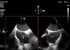


-
Remainder of IV heparin is given to achieve target ACT > 300 sec.
-
A stiff 0.035” wire is introduced into LA (Confida) through the sheath. Then the transseptal sheath and 18 Fr sheaths are removed.
Insertion of Steerable Guide Catheter
-
Steerable guide catheter (SGC) is inserted in a negative deflection into the femoral vein with the support of Confida wire up to RA (Figure).
-
Turn +/- knob on SGC back to neutral and enter LA. If resistance, corkscrew in gently or turn SGC knob (-) negative to straighten SGC to give better pushability. Use fluoroscopy and echocardiogram to help. In case the dilator or guide does not go, then balloon dilatation (usually 10-12 mm x 40 mm balloon) of interatrial septum is necessary.
-
Once the SGC and dilator is parked in LA, ask the echocardiographer to show the guide. SGC is parked on the stabilizer without any gap between the proximal SGC and the stabilizer portion. A screw should be used to anchor the SGC on top of stabilizer. A ridged appearance in the echo arises from the dilator. With the wire still in LA, dilator alone comes out (check in TEE) gently into guide.
-
After ensuring at least 1 cm of steerable guide catheter is inside LA, wire is pulled back into the dilator. Later both dilator and wire come out with wire inside the dilator – with a gentle negative suction at the SGC port to avoid air entry. Once the wire and dilator are outside, the Y connector port of the SGC is closed with a finger while gentle aspiration is continued through the external port. Then the SGC external port is connected to pressure line to monitor LA pressure.
Insertion and Steering of Clip Delivery system
-
CDS (Steerable sleeve catheter and handle catheter with clip) is inserted into SGC with a “waterfall”: blue-to-blue alignment is maintained (Figure) until it is locked with the SGC system. This is essential for 1:1 torque movement in the required direction with the movement of knobs. CDS is advanced though the SGC (figure) in specific, controlled hand movements. This will avoid sudden jerky movements of CDS inside LA.
-
Once the clip is inside LA, ask the echocardiographer to follow the clip. Usually both can be seen in aortic valve short axis view at 45-60 degrees, mid esophageal TEE view. In case we lose space to straddle, the entire system with the stabilizer can be retracted together slightly backwards using fluoroscopy and echocardiogram to enable straddling (figure). Once straddling is done, the clip needs to be steered to make it perpendicular to the MV annular plane. M (medial) knob movement, posterior rotation of SGC (clockwise movement of SGC) usually gets the CDS perpendicular to the MV. In case of an aorta hugger position, a + knob movement on SGC is required with gentle anterior torque with SGC and lateral movement of the stabilizer to advance the system. During steering, the clip handle may be exposed out of the sleeve guide catheter. Loosen the screen and retract the clip handle gently backwards to remove the slack. Also, keep an eye on the straddle to avoid under/over straddle. MPSS is the pneumonic that helps to remember the knobology movement (Medial, Posterior, Straddle, Sleeve).
-
Now we need to keep the clip perpendicular to the line of coaptation (LOC) using fluoroscopy and TEE. Need to use Bicom Xplane to LVOT view, 3D En-face view to ensure the same. In Bicom, single clip arm is seen while in LVOT, both the closed clip arms are seen.
-
Before opening the clip arms to 60 degrees, we need to remove the tension in the system by doing jiggle motion of the clip handle. Jiggle movements should be very controlled in a clockwise, counterclockwise fashion to ensure that the clip is perpendicular to the LOC on TEE.
Optimize Clip Orientation
-
Gripper line up – until blue line slowly, just after blue line is fine.
-
Lock line up – until blue line slowly, just after blue line is fine.
-
Open clip arm – arm opener to 60 degrees
-
Jiggle movement of CDS handle catheter in clockwise or counterclockwise direction (controlled fashion) to loosen up the tension in the system and on RAO view take the parallax out of the clip arms while on 3D to confirm orientation.
-
Confirmation of clip arm position to MV plane: In fluoroscopy, CDS should be 90 degrees angle to the SGC for optimal “M”. On TEE Bicom view, the shaft of CDS should be perpendicular to MV annular plane. Watch out for Over “M” and shaft turned >90 degrees and slanted against mitral annulus.
Ready to Enter into LV
-
Check trajectory by advancing the CDS slightly forward towards the MV annulus without crossing the valve. Should optimize trajectory typically with (+) knob to at least 60-90 degrees and anterior SGC torque to move the clip more anterior. May need to remove some “M” to maintain perpendicular trajectory of clip to MV annulus in Bicom view.
-
When entering LV, left hand should hold the SGC while the right hand holds the clip handle (Figure). We may need to close the clip during LV entry of the clip near commissures or large flail to avoid getting leaflet caught against gripper or if it is a second clip. On fluoroscopy, check to make sure clip has not rotated; may need to go opposite in rotation on CDS handle vs before (e.g., if clockwise before to orient clip, may need to go counterclockwise to avoid clip spinning as it enters LV). In addition, check on fluoro the CDS shaft remains straight instead of medial or lateral deflection. If so, may need to adjust M knob to correct.
Grasping Leaflets in LV
-
Open clip arm to 150 degrees
-
Check clip arm orientation on 3D TEE by dropping the gain
-
Pull clip fastener up under TEE gently. Try to grasp anterior mitral leaflet first followed by posterior mitral leaflet. Gentle and steady posterior torque of SGC is essential to grasp posterior leaflet. Keep HR at 50-60 with tidal volume around 300-350cc.
-
Continue to optimize grasping by slight SGC posterior/anterior torque, maintaining clip orientation on fluoroscopy, some “M” or “+” knob adjustment if needed.
-
Ensure capture of both the leaflets over the clip arms in Bicom view X-plane to LVOT view. Grippers down in diastole slowly. Look for gripper bounce on both AML and PML. Let the echocadiographer know! Slowly close the clip arm to 60 degrees; may need to advance CDS handle with slightly posterior SGC torque to reduce leaflet tension and maintain leaflet insertion especially in restricted pathology (Secondary MR).
-
Ensure adequate leaflet capture before closing the clip further; avoid multiple closures to prevent leaflet damage.
-
Lock the clip. Close the clip under color on Bicom/LVOT views; may need to advance CDS handle to further reduction leaflet tension +/- slight posterior SGC torque especially in case of secondary MR and short posterior leaflet.


Assessment of Clip after Grasping
-
Check leaflet insertion by measuring residual leaflet length vs baseline, and immediately adjacent (lateral, medial) to the clip.
-
Check MR reduction, MV gradient, PV flow pattern. Check LA pressure/V wave changes in hemodynamic tracings. On TEE use 4-chamber, Bicom X plane to LVOT and 3D En-face with and without color.
Clip Deployment
-
Once the interventionalist and echocadiographer are convinced about good grasp with appropriate reduction of MR, and improvement in hemodynamics, clip will be deployed.
-
Go to LAO 30 to 45 degree to visualize both clip arms: Ensure arm opener is not able to open clip arms – by going to neural and opening to 270 degree arc; Look for whether clips are opening or not: They should not open up. In case they open up, then open the lock arm again and close it; and redo the same to make sure that the clip arms do not open up.
-
Then turn knob clockwise tight to close clip tightly.
-
Drips on; Grippers cap off – gripper line out – floss in same direction parallel to the gripper level; Floss both lines.
-
Lock line cap out; unwind the two strands against the rubber cap; floss both the threads; remove lock line thread slowly
-
Ensure arm opener is not able to open clip arms – by going to neutral and opening to 270 degree arc; Look for whether clips are opening are not: They should not open up; Then go back to neutral.
-
Remove safety pin.
-
Open arm opener – Expose the grooves.
-
Go for at least eight rotations with the actuator knob; then pull the pin.
-
At the same time as the eight rotation-turn, unscrew the clip handle screw; retract the CDS handle backward slowly to free the needle from the clip to deploy the clip. Watch under fluoroscopy and TEE; If needle is too posterior or anterior, try to center; this happens when a lot of posterior SGC guide torque is in place.
-
Gripper line thread come out slowly under fluoroscopy to make sure the pin is not pulled towards the valve and clip to risk interaction.
-
Two kinds of clip deployment:
-
Gripper line first: In case of thin leaflet, small LA, not much slack remaining between the pin and the CDS; Gripper line is removed slowly first after informing the echocardiographer before removing the pin; later rest of the steps happen.
-
IFU method: Here Gripper line is removed at the end.
-
Undo the “+” knob and gently remove the “M” knob as you retract the CDS back into the SGC under TEE and fluoroscopy guidance.
-
Once CDS inside SGC, remove the CDS and apply gentle negative suction at the SGC external port gently to avoid air entrapment. Look for the silver circle in the CDS as you remove the CDS. Once it is visible, the CDS is removed en-bloc with its introducer.
Assessment after First Clip
-
Assess the grasp by looking at the tissue grasped by MitraClip in 3D echo along with the severity of MR. Effect of MitraClip on LV inflow obstruction assessed by measuring mean gradient across MV should be noted. Also effect of MitraClip on pulmonary venous flow pattern that either should become blunted or is normalized after clip. In addition, LA pressures measured by SGC should drop down. In general MR should drop down at least 2 grades from baseline with acceptable MV gradient (mean MV gradient < 5 mmHg). If MR is more than 2+ with mean MV gradient < 5 mmHg, additional clip can be contemplated if anatomy is feasible. If it is decided to proceed with second clip, steps under Insertion and Steering of CDS, Optimize Clip Orientation, Ready to Enter into LV are repeated. An important step is to keep the clip closed while entering LV from LA. Need to take the help of fluoroscopy to get the second clip parallel to the first clip. Often second clip is much faster than first clip and it makes the first clip more stable. Repeat the same anatomical and physiological assessment to determine if a third clip is necessary.
-
If an additional clip is not needed, then remove SGC, assess ASD size and shunt direction, remove the SGC with two hands slowly, then perform groin closure. Usually, the ASD does not need to be closed; ASD closure can be considered before removing SGC in case of right to left or bidirectional shunt ASD, severe RV dysfunction, severe tricuspid regurgitation, or severe pulmonary hypertension.